Klarian completes Innovate UK project on non-ideal flow dynamics in pipelines
Recently, Klarian completed a project for Round 7 of Innovate UK’s Analysis for Innovators (A4I) grant funding programme.
We wanted to improve the accuracy of our flow analysis in challenging locations for better pipeline monitoring. Working with Astute, experts in computational fluid dynamics, we modelled how bends impact flow turbulence in pipelines. To quote some feedback from Innovate UK, it was “a perfect example of a three-month project.”
Pipeline monitoring with ultrasonic flow sensors
Pipeline monitoring is about collecting and analysing data to give you an understanding of how they are operating. There are many pipeline monitoring systems; sensors are one of the most common. A pipeline usually has many sensors along its length, including those measuring flow.
Ultrasonic flow sensors use ultrasound to measure flow. They work by emitting high-frequency sound waves into the fluid flow and measuring the time it takes for the waves to travel upstream and downstream against the flow. The difference in time between the upstream and downstream travel of the sound waves is proportional to the velocity of the fluid flow. If you know the pipeline diameter, you can calculate the flow rate.
While it’s all very well using ultrasonics for long, straight pipes, what happens when conditions are not ideal? Pipelines crisscross some of the world’s harshest and most remote terrain, which can cause disruptions to the flow.
To achieve high accuracy using clamp-on ultrasonic flow sensors, you need to understand the turbulent conditions within the pipe.
Understanding non-ideal flow dynamics
Klarian aims to achieve high accuracy for every pipeline scenario, whether we’re looking at a simple straight line or a bespoke situation, which may include a variety of bends and other flow disruptions. We tackled this challenge via an Innovate UK funded mini project as part of the A4I Round 7 call.
The proof-of-concept project involved working with the computational fluid dynamics team within Astute. Astute is a multi-university partnership which delivers collaborative projects with industry. Their expertise focuses on advanced materials, computational modelling and manufacturing systems.
Initially, we created a computational fluid dynamic (CFD) model to mimic an experimental setup at the National Engineering Laboratory. We used the experimentally generated data to tweak and validate the CFD model. The next step was to see what happened when we modified the model with several bends to simulate our trial sensor deployment at Manchester Airport.
The results: improved accuracy
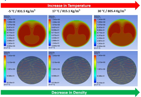
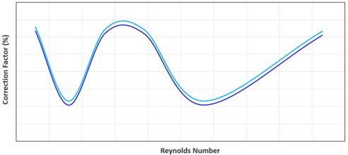
We generated turbulence data across a range of flow and temperature profiles for the four deployed sensors (figure 1). Using this data, we then corrected and calibrated the sensors in Manchester. The result was significant: we halved the sensors’ disagreement with the highlight accurate in-line fiscal (figure 2).

Figure 1: Example showing some of the velocity turbulence profiles generated via CFD for a range of temperatures

Figure 2: Correction factors applied to the sensors to compensate for non-ideal turbulence conditions
Greater flow accuracy means a more accurate understanding of your asset. If you understand how your asset is performing, you can make the best decisions for safer, greener and more efficient operations.